INDUSTRY SOLUTION

Aerospace Vibration and Modal Testing

Non-contact response and modal measurement for airframes, blades, thin-wall components and complex lightweight structures.

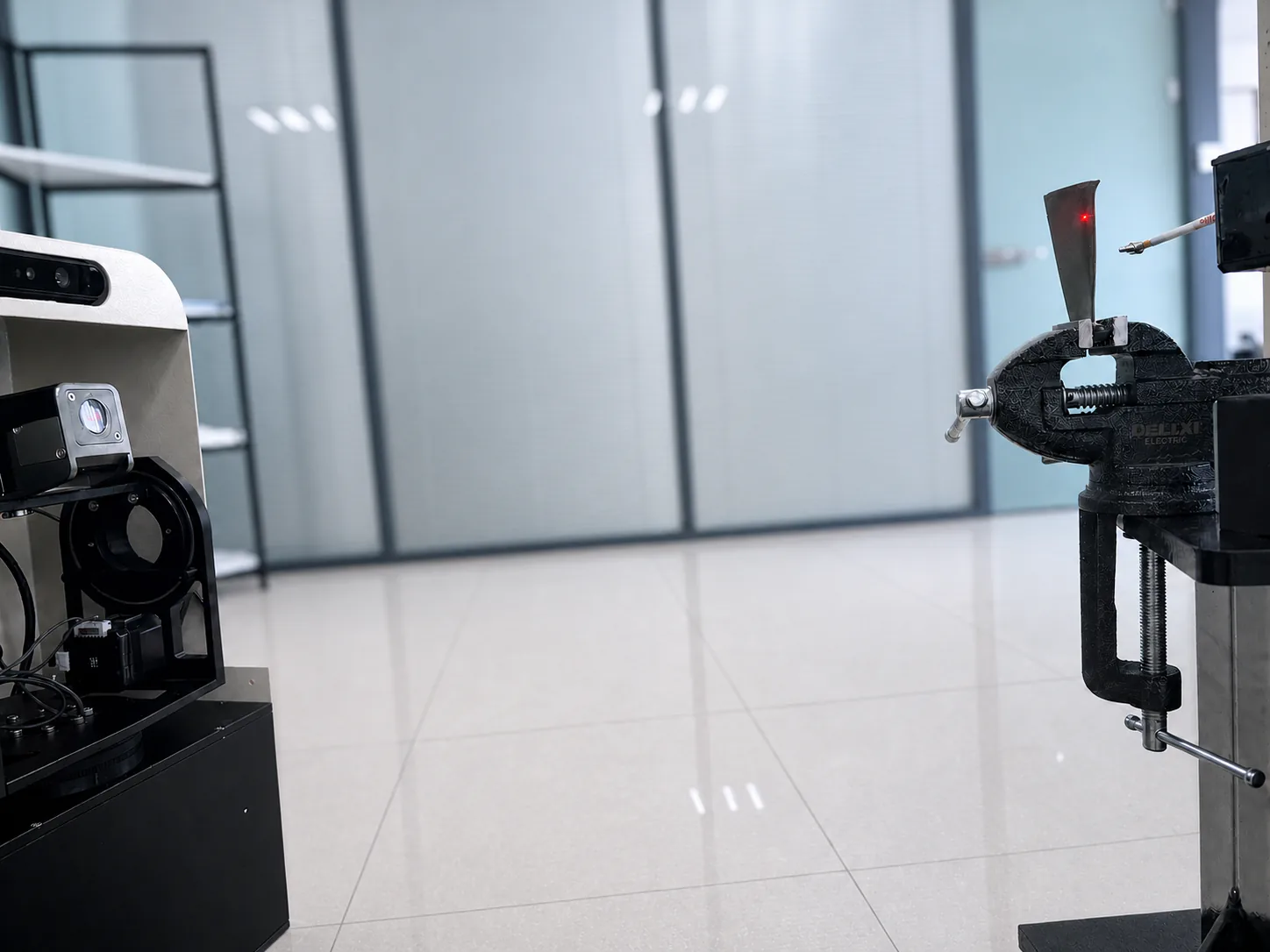
Aerospace non-contact vibration and modal testing application

Non-Contact Testing for Aerospace Structures

Aerospace components often combine thin walls, curved surfaces, lightweight construction and dense measurement grids. Attached sensors can alter local mass or stiffness, while complex surfaces make placement and cabling difficult. Laser vibrometry supports response acquisition from blades, thin-wall parts and assembled structures and can be combined with reference channels and modal-analysis software.

Typical Measurement Tasks

01

Measure operating vibration, ODS and localized anomalous response regions.

02

Identify natural frequencies, damping and mode shapes and compare them with finite-element predictions.

03

Scan blades and thin-wall structures with dense, non-contact measurement grids.

Recommended Products and Configuration Logic

Use the Gimbal Scanning Laser Vibrometer for remote multi-point scans; the Gantry 3D Scanning Laser Vibrometer System for laboratory three-dimensional response testing; and the modal-analysis workflow in Technology for calibration, review and ODS/OMA/EMA analysis. Final configuration depends on structure size, surface, distance, frequency band and excitation.

Suggested Test Workflow

  1. Define the objective, boundary conditions, measurement coordinates and result units.
  2. Plan points, reference channels, excitation or operating condition, then confirm return signal and line-of-sight direction.
  3. Complete calibration, synchronized acquisition and raw-data review while storing conditions and software versions.
  4. Choose ODS, OMA or EMA based on excitation observability and verify frequency, damping and mode-shape stability.
Scroll to Top