
Technical review: Mr. Sun, Technical Manager
Summary: Laser vibrometers avoid sensor mass loading, but the measurement can still be affected by optical return, beam angle, stand-off distance, target motion, environmental disturbance and acquisition settings. A structured quality review separates instrument limitations from setup and interpretation errors.
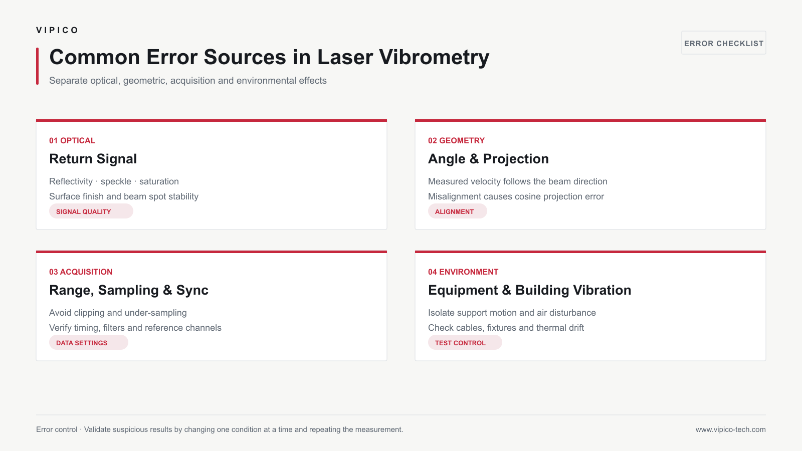
1. Insufficient or Unstable Optical Return
Dark, highly curved, translucent, rough or specular surfaces can cause weak or intermittent return. Monitor signal-quality indicators and test representative points before a full scan. Surface treatment may help, but document any tape, coating or marker added to the structure.
2. Incidence-Angle and Directional Error
A single-beam vibrometer measures velocity along the optical axis. If the motion direction differs from the beam direction, the measured component follows a cosine relationship. Large angle changes across a curved target can therefore create apparent spatial differences that are geometric rather than structural.
3. Stand-Off Distance and Beam Position
Long paths can reduce optical return and make beam placement more sensitive to alignment, air movement and structural drift. Verify focus, spot position and line of sight at the farthest and most oblique points, not only at the center of the target.
4. Environmental Vibration and Acoustic Disturbance
Tripods, optical tables, floors and enclosures can move. Airflow and temperature gradients can disturb long optical paths. Use a stable support, shorten unsupported paths where practical, check background measurements and separate environmental components from target response.
5. Speckle and Dropout
Coherent light reflected from a rough surface forms speckle. Relative motion can change the received speckle pattern and cause amplitude fading or phase disturbance. Small changes in beam position, optical geometry or surface treatment can improve stability.
6. Sampling and Signal-Processing Errors
| Risk | Observed symptom | Control |
|---|---|---|
| Aliasing | False low-frequency components | Use adequate sampling and anti-alias filtering |
| Clipping | Flattened peaks and harmonics | Adjust range and verify pilot measurements |
| Leakage | Smeared spectral energy | Set record length and window for the signal type |
| Low resolution | Closely spaced modes merge | Increase record length and frequency resolution |
| Poor synchronization | Unstable phase or FRF | Use common timing and verified reference channels |
7. Scanning-Specific Errors
During a long scan, operating state, excitation amplitude or temperature may change. Point-coordinate errors, gimbal settling, surface-angle variation and missed points can distort mode shapes. Use pilot points, repeat checks and a documented rejection rule.
Troubleshooting Sequence
- Confirm the target is actually moving within the expected range.
- Check optical signal and beam position.
- Review instrument range, bandwidth and clipping.
- Measure background vibration with the target inactive.
- Repeat one point and compare time histories and spectra.
- Change one setup variable at a time.
- Record the final geometry and processing settings.
Frequently Asked Questions
Does a strong optical return guarantee an accurate result?
No. It is necessary but not sufficient. Directional sensitivity, sampling, environmental motion and interpretation must also be correct.
Should retroreflective tape always be used?
No. Use it only when needed and consider its added mass or stiffness, especially on miniature or lightweight targets.
How can scanning consistency be checked?
Repeat selected reference points during or after the scan and compare signal level, spectrum and phase under the same operating condition.
Related Products and Resources
- Gimbal Scanning Laser Vibrometer
- Laser Vibrometry Technology
- Application Solutions
- Contact VIPICO Engineering