
Technical review: Mr. Sun, Technical Manager
Summary: Blades combine lightweight construction, curved geometry, closely spaced modes and strict boundary-condition requirements. Gimbal scanning laser vibrometry can acquire dense non-contact response grids while minimizing sensor loading and adapting to a wider field of view.
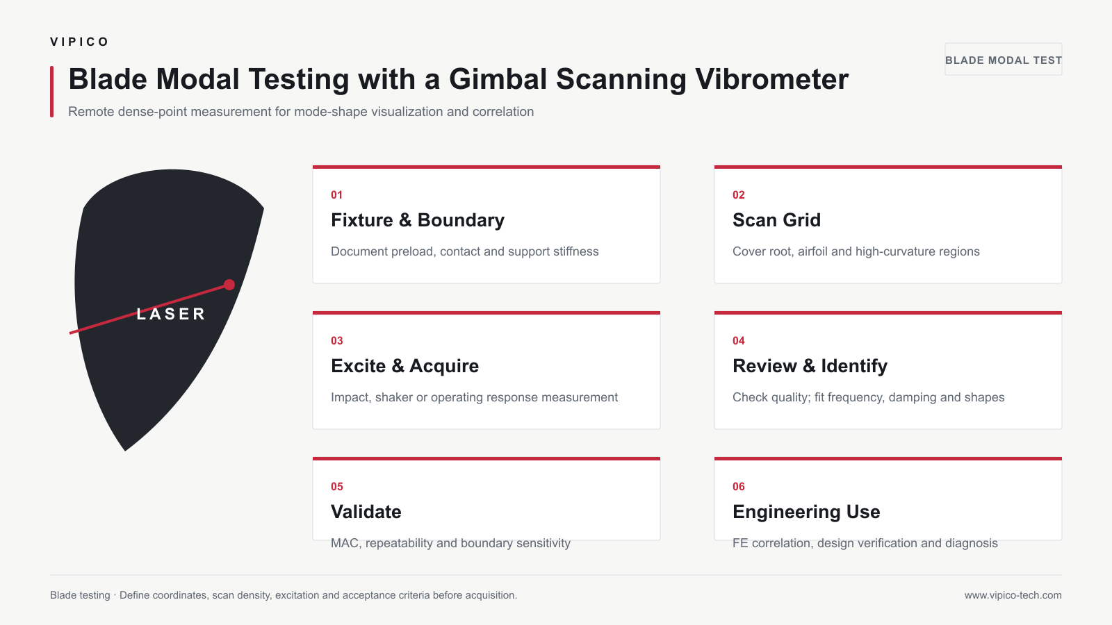
Why Blade Testing Is Challenging
- Thin sections and low local mass make attached sensors influential
- Curvature changes the beam incidence angle across the surface
- Torsional and bending modes may be closely spaced
- Root fixtures strongly affect frequency and damping
- Composite blades may show anisotropy and local defects
- Rotating and non-rotating tests require different safety and reference strategies
1. Define the Boundary Condition
Decide whether the test represents a free-free component, a clamped root, an assembled stage or an operational condition. Record fixture geometry, bolt torque, preload and contact surfaces. Modal comparisons are meaningful only when the boundary conditions are equivalent.
2. Build a Curved-Surface Measurement Grid
Use a coordinate system that represents spanwise, chordwise and thickness directions. Increase point density near the root, edges, geometric transitions and regions where torsional behavior is expected. Check beam access and incidence angle for every point.
3. Choose Excitation and References
| Objective | Recommended approach | Reference requirement |
|---|---|---|
| Controlled FRF and modal parameters | Impact hammer or shaker EMA | Measured input force and synchronized response |
| Operating deformation at an order/frequency | ODS under operating excitation | Phase or tachometer reference where needed |
| Modes under realistic operation | OMA when assumptions are satisfied | Synchronized response channels or repeated stationary operating states |
4. Configure the Scan
Set frequency bandwidth and record length to resolve expected bending and torsional modes. At each point, review optical return, clipping and stability. Allow gimbal settling and use a repeatable reference point to monitor drift during long scans.
5. Analyze and Validate
Inspect spectra, FRFs, coherence, stabilization diagrams and mode shapes according to the selected method. Use MAC or other correlation metrics when comparing repeated tests or finite-element predictions. Review whether apparent asymmetry is physical or caused by optical geometry and point quality.
Finite-Element Correlation
Map measured and calculated coordinates consistently. Compare frequency, shape and boundary assumptions before adjusting material properties. Large discrepancies may result from fixture stiffness, joint representation, manufacturing tolerance or insufficient spatial resolution—not only from material modulus.
Recommended Deliverables
- Blade and fixture description with photographs
- Coordinate system and scan-point map
- Excitation, references and acquisition settings
- Point-level data-quality review
- Natural frequencies, damping estimator and mode shapes
- ODS/OMA/EMA method statement
- Finite-element correlation and stated limitations
Frequently Asked Questions
Can one optical view capture the full blade?
It depends on geometry and line of sight. A gimbal provides wide pointing coverage, but hidden surfaces may require additional views and coordinate registration.
How should torsional modes be captured?
Use points on both sides of the torsional axis or across the chord so opposing motion can be resolved. A single centerline may miss important torsional behavior.
Can the method be used on rotating blades?
Operational measurement is possible only with an appropriate safety enclosure, optical access, synchronization and motion-tracking strategy. The configuration differs significantly from a stationary modal test.
Related Products and Resources
- Gimbal Scanning Laser Vibrometer
- Laser Vibrometry Technology
- Application Solutions
- Contact VIPICO Engineering