
Technical review: Mr. Sun, Technical Manager
Summary: The VIPICO gimbal scanning laser vibrometer and modal analysis system combines programmable beam pointing, laser Doppler vibration measurement, synchronized acquisition and structural-dynamics analysis. It is intended for targets where dense spatial data, long stand-off distance or minimal sensor loading are important.
What the System Is Designed to Do
A conventional single-point laser vibrometer provides the response at one location. A gimbal scanning system adds controlled angular positioning so the beam can address a defined grid over a larger structure. Each point is linked to response data, allowing engineers to review spatial vibration behavior rather than isolated traces.
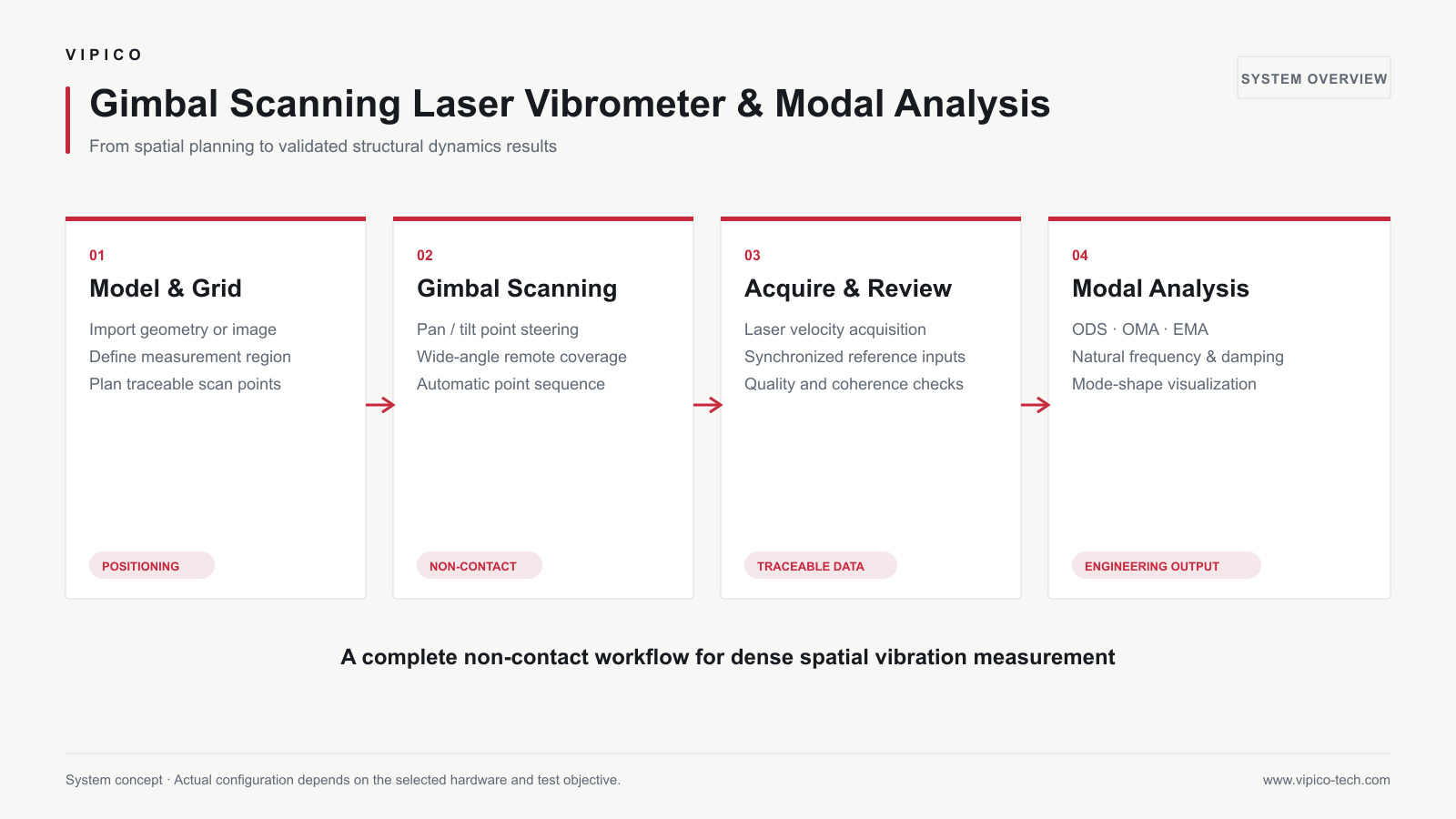
The system is designed around a complete measurement chain: target definition, geometric registration, scan planning, non-contact acquisition, signal-quality review and modal or operating-deflection-shape analysis.
Core System Architecture
| Subsystem | Primary function | Engineering value |
|---|---|---|
| Precision gimbal | Directs the optical beam to programmed points | Supports wide fields of view and repeatable point planning |
| Laser vibrometer | Measures vibration velocity or derived displacement without contact | Avoids sensor mass loading on the test structure |
| Dynamic acquisition | Captures response and optional reference channels synchronously | Preserves phase relationships for structural analysis |
| Planning and review software | Associates geometry, point coordinates and measured responses | Improves traceability and reduces manual point-management errors |
| Modal-analysis software | Processes spectra, ODS and modal parameters | Turns measurements into interpretable engineering results |
Where Gimbal Scanning Adds Value
- Large or curved structures that cannot be covered by a narrow optical scan angle
- Remote targets where sensor installation is impractical
- Lightweight parts whose dynamics may be altered by accelerometer mass
- Dense point grids used for ODS, EMA or test-to-model correlation
- Repeated validation tasks requiring a reusable point plan
Recommended Project Inputs
Before configuration, define the target dimensions, stand-off distance, frequency range, expected vibration level, surface condition, line-of-sight constraints, excitation method and required outputs. These determine the optical arrangement, point density, sampling parameters and analysis route.
Typical Measurement Workflow
- Define the engineering question and acceptance criteria.
- Establish the target coordinate system and field of view.
- Create the measurement grid and check beam accessibility.
- Configure acquisition bandwidth, sampling and reference channels.
- Run a pilot point and confirm signal quality.
- Execute the scan and review each point for clipping, dropouts or poor return.
- Generate spectra, ODS or modal results with documented test conditions.
Frequently Asked Questions
Does a gimbal scanner replace every galvanometer scanner?
No. Galvanometer systems can be advantageous for very fast scanning over a compact angular field. Gimbal scanning is particularly useful when field of view, stand-off distance and large-target coverage are more important.
Can the system perform modal analysis?
Yes, when the measurement plan includes the required response and reference information. The appropriate method—ODS, OMA or EMA—depends on excitation, available inputs and the engineering objective.
What surfaces are suitable?
Signal quality depends on optical return, angle and distance. Matte or weakly reflecting surfaces may require surface preparation or retroreflective treatment, which should be documented as part of the test.
Related Products and Resources
- Gimbal Scanning Laser Vibrometer
- Laser Vibrometry Technology
- Application Solutions
- Contact VIPICO Engineering